¶ TOOCAA 5-in-1 Rotary for L2
¶ Get to know TOOCAA 5-in-1 Rotary for L2
¶ Product Description
TOOCAA 5-in-1 Rotary for L2 is a versatile rotary accessory designed for precision machining of various materials. It has 5 types of accessories that can handle different types of materials in multiple scenarios, supporting the needs of hobbyists and professionals seeking high-quality engraving and cutting solutions. Applicable to manual projects, model making, small batch production, and school education.
- 【Flexible Adjustment】5-in-1 multifunctional laser rotating accessory. The 180° adjustable three-finger clamp supports 90% of daily cylinders, spheres, and special-shaped objects. You can finish your creation with various materials like wine glasses, jewelry, baseball bats, rings, etc.
- 【Exclusive Patent】The world's only patented design of 3-second elastic quick-release jaws. By quickly changing different types of locking parts, you can perform 360° engraving on different diameters of objects. Improve the creation efficiency by reducing the steps of disassembling and storing parts.
- 【Fast and Precise】The maximum engraving speed of the laser rotary attachment can reach 360°/sec. It is equipped with a high-precision, high-torque stepper motor with a minimum step angle of 0.02°, letting you capture all the details in your creation.
- 【Efficient Service】Please contact us if you encounter any problems with the swivel attachment, TOOCAA product experts will provide friendly customer service and professional technical support within 24 hours.
¶ Product Specification
| Product Name | TOOCAA 5-in-1 Rotary for L2 |
| Product Size | 286 × 88 × 128 (mm) |
| Product Weight | Net weight:2.0kg |
| Types of Accessories | Roller Rotary, Chuck Rotary, Sphere Rotary, Ring Rotary, 180° adjustable flip mode |
| Engraving Diameter Range | Roller Rotary:5-200(mm) Chuck Rotary:0-140(mm) Sphere Rotary:25-120(mm) Ring Rotary:12-100(mm) |
| Chuck Angle Adjustment Range | 0°-180° |
| Compatible Machines | TOOCAA L2 |
| Compatible Software | TOOCAA Studio\LightBurn |
¶ Unboxing inspection
¶ Applicable object reference
We need to use different types of accessories when engraving some large or irregular consumables. The following is a reference for the objects that the 5 types of accessories are suitable for.
| Types of Accessories | Definition of Product Function | Diameter Range | Accessories Pictures |
|---|---|---|---|
| Roller Rotary | Applicable to irregular cylinders and extra-long objects | 5-200(mm) |
 |
| Chuck Rotary | Applicable to objects with round or non-round bases | 0-140(mm) |
 |
| Sphere Rotary | Applicable to spherical objects | 25-120(mm) |
 |
| Ring Rotary | Applicable to the outer ring | 12-100(mm) |
 |
| 180° Adjustable Flip Mode | Applicable to special-shaped beveled cylinders and inner rings | / |
 |
¶ Roller Rotary Accessories Operation Tutorial
Insert the clutch components into the chuck body assembly and secure it with the screws.
TIPS:Adjust the interface angle by twisting the knob of the rotating accessory can for easy alignment and proper insertion of the clutch components.
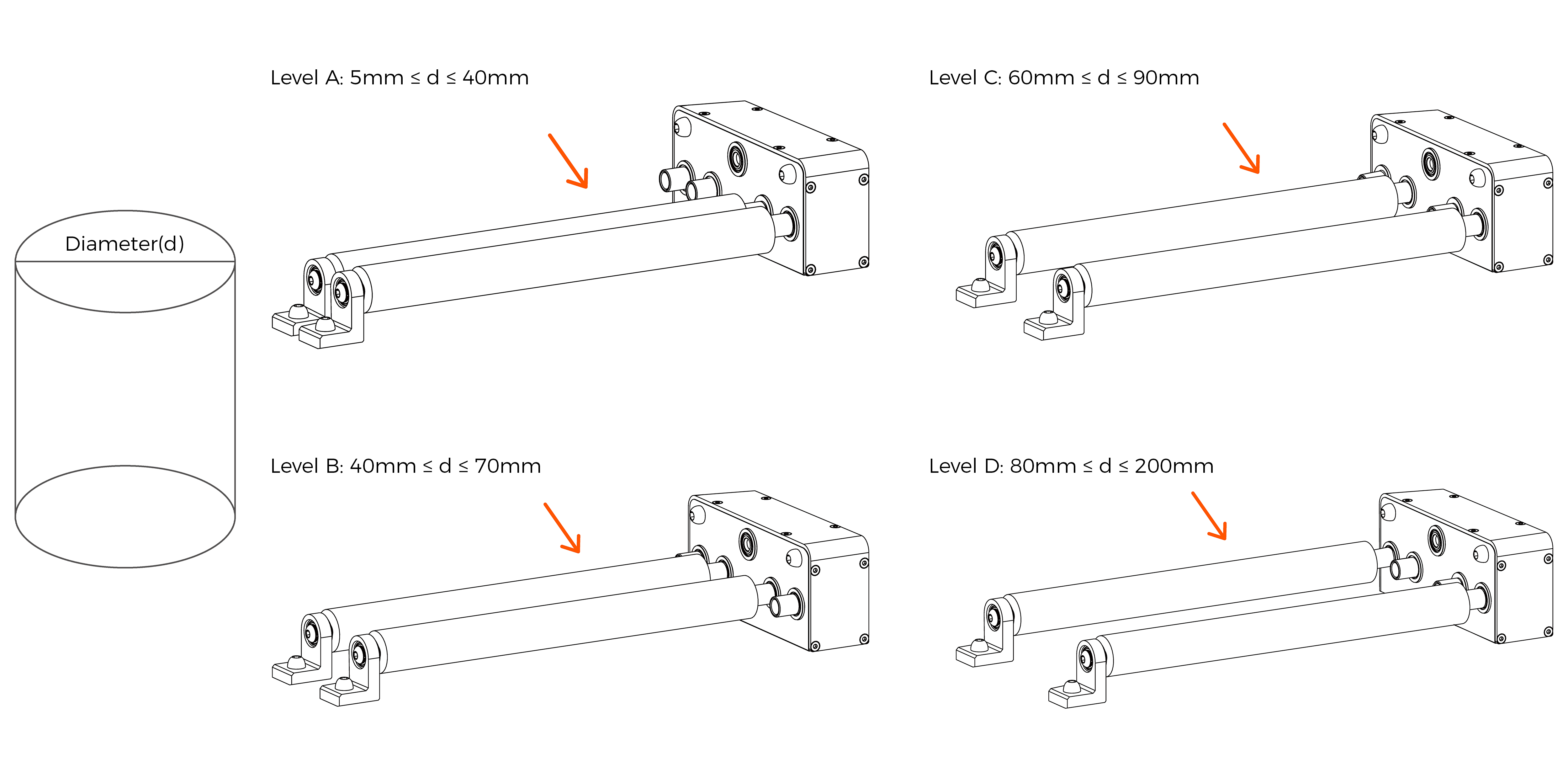
Measure the diameter of the material being cut with a vernier caliper or tape measure and select the appropriate clutch components based on the diameter of the material being cut/engraved.
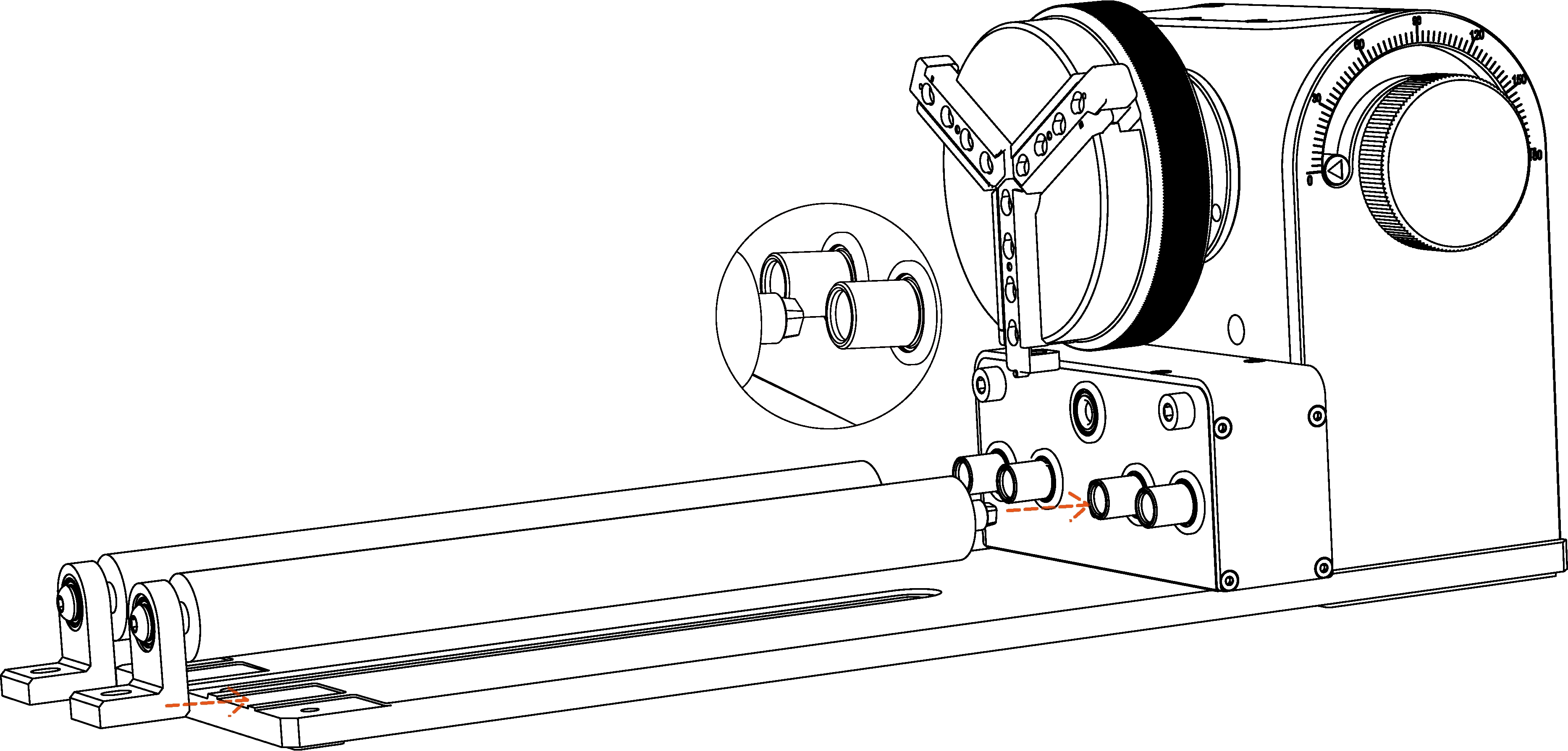
Insert the roller assembly into the clutch components along the gap at the bottom of the chuck body assembly.
TIPS:By twisting the knob on the chuck body assembly of the rotating accessory to adjust the interface angle inside the clutch components, the roller assembly can be easily aligned and correctly inserted.
Note:The screw holes at the rear of the roller assembly should be aligned perfectly with the screw holes on the chuck body assembly of the swivel attachment to be properly connected.
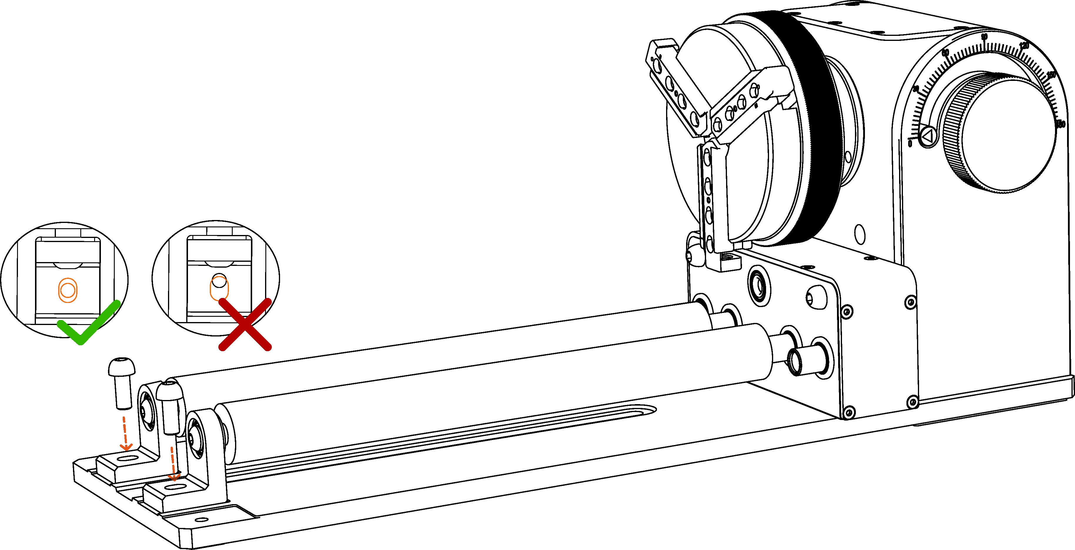
Secure the roller assembly with screws.
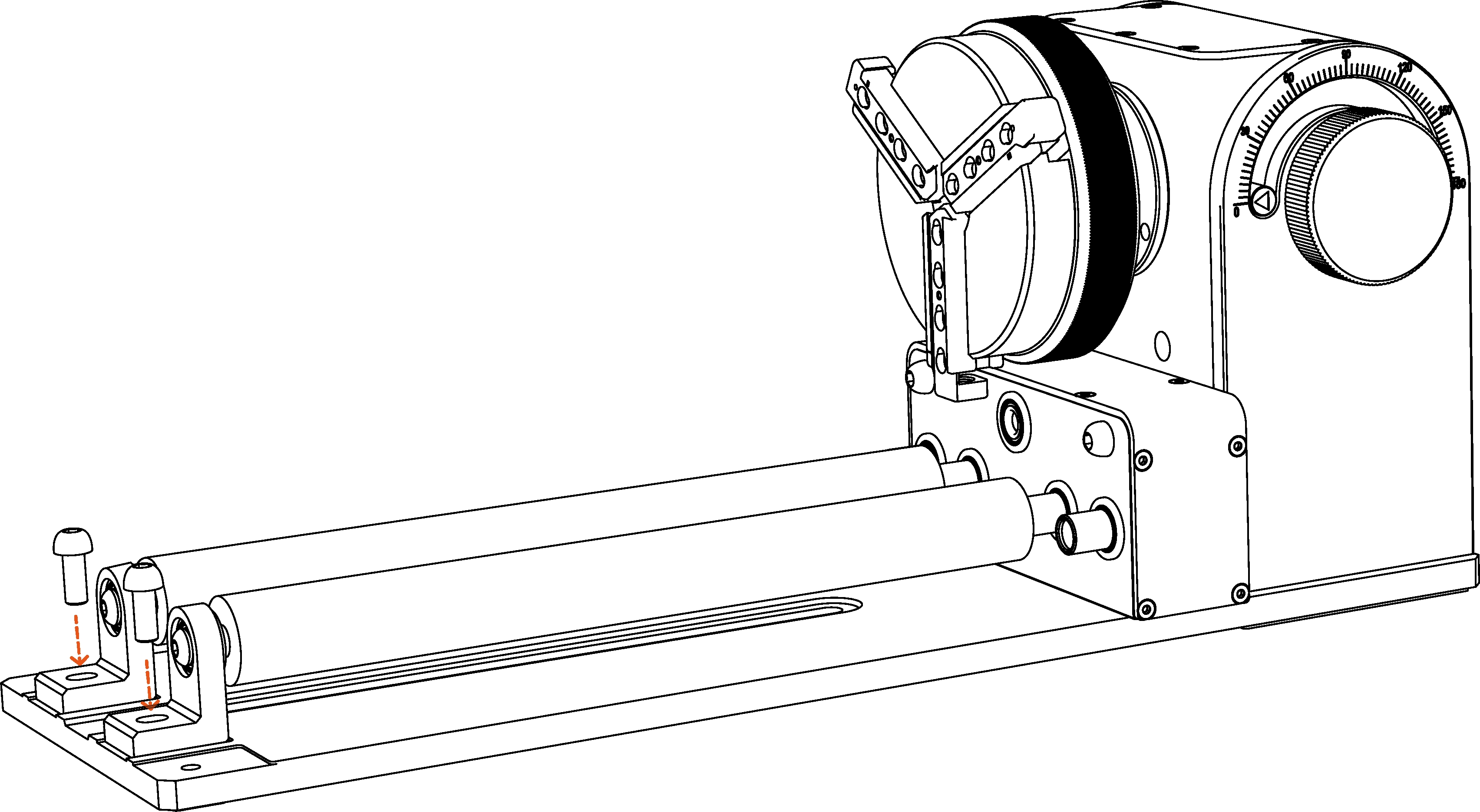
Note:Please rotate and move the roller assembly in a small range after fixing it to ensure that the roller assembly can be used normally. If it is loose, it means that the roller assembly has not been installed properly. Please remove the roller assembly and recalibrate and install it.
¶ Chuck Rotary Accessories Operation Tutorial
As shown in the figure. Adjust the chuck knob clockwise to unlock, and adjust the chuck knob counterclockwise to lock. The chuck can be expanded or contracted by adjusting the chuck knob to facilitate the insertion of the double-step jaw components.
Press the button on the top of the chuck and insert the double-step jaw components into the chuck of the appropriate cutting/engraving material size.
¶ Sphere Rotary Accessories Operation Tutorial
As shown in the figure. Adjust the chuck knob clockwise to unlock, and adjust the chuck knob counterclockwise to lock. The chuck can be expanded or contracted by adjusting the chuck knob to facilitate the insertion of the chuck needle.
Press the button on the top of the chuck and insert the chuck needle into the chuck of the appropriate cutting/engraving material size.
Insert the stock column assembly along the gap at the bottom of the chuck body assembly.
Fix the chuck body assembly with screws.
¶ Ring Rotary Accessories Operation Tutorial
As shown in the figure. Adjust the chuck knob clockwise to unlock, and adjust the chuck knob counterclockwise to lock. The chuck can be expanded or contracted by adjusting the chuck knob to facilitate the insertion of the chuck needle.
Press the button on the top of the chuck and insert the chuck needle into the chuck of the appropriate cutting/engraving material size.
¶ 180° Adjustable Flip Mode Accessories Operation Tutorial
The tilt angle of the chuck body assembly can be adjusted by the side knob. When the tilt angle is appropriate, tighten the knob to fix it.
Note:Before adjusting the tilt angle of the chuck body assembly, the roller assembly and clutch components must be removed.
¶ Support Module Operation Tutorial
The support module consists of a stock column assembly, a stock pulley bracket assembly, and a stock bottom plate assembly, which can be connected as shown in the figure.
Note:Pay attention to the direction when installing the stock pulley bracket assembly into the stock column assembly.
The support module is specially designed for longer consumables. The height of the support module support wheel can be adjusted by turning the knob. By holding up the tail of the cutting/engraving materials, the longer cutting/engraving materials can be kept horizontal, which is convenient for high-quality engraving and cutting work.
¶ Device Connection Operation
Remove the black silicone pad from the TOOCAA L2 foot pad, connect the heightening feet to the foot pad, and increase the height of the machine.
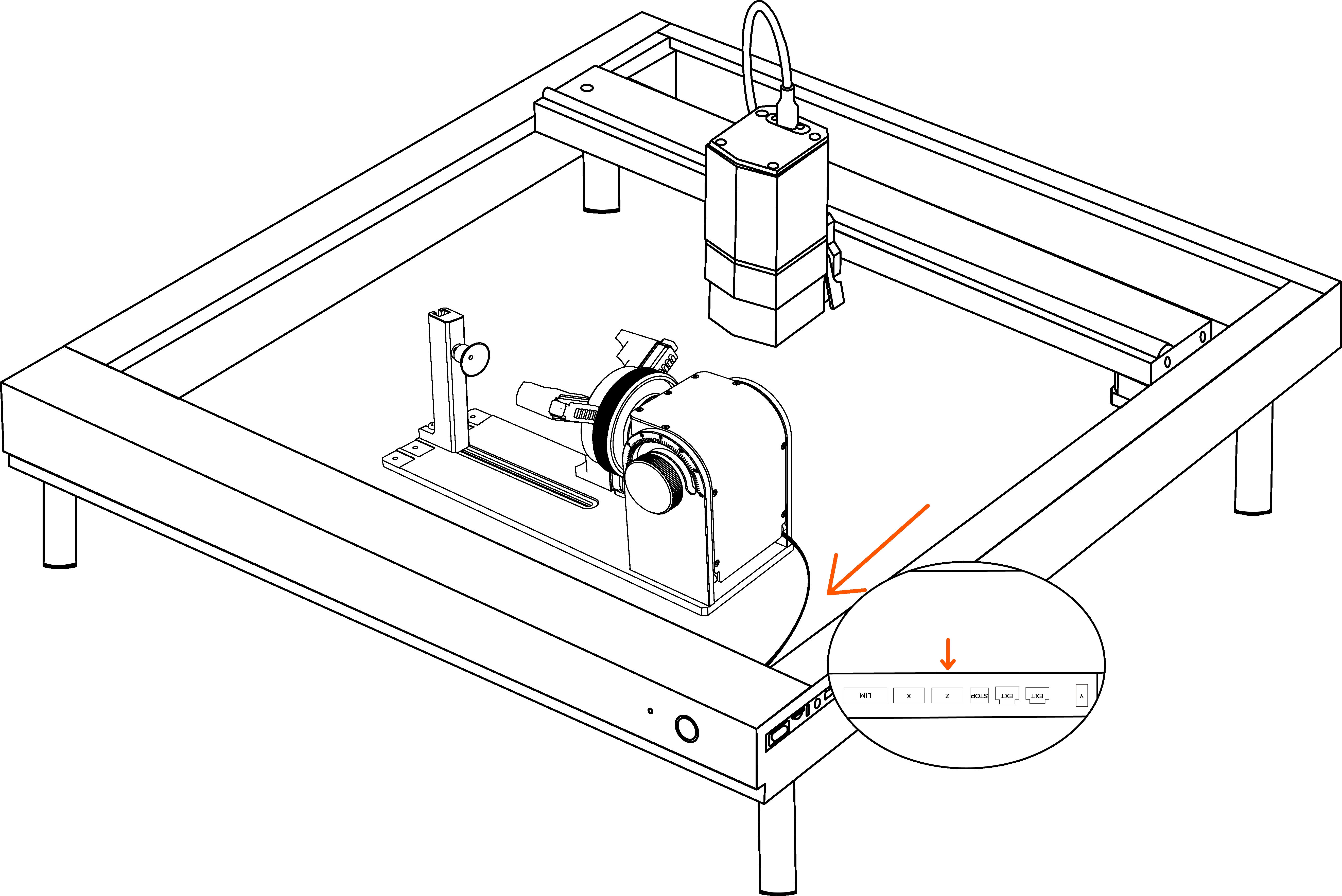
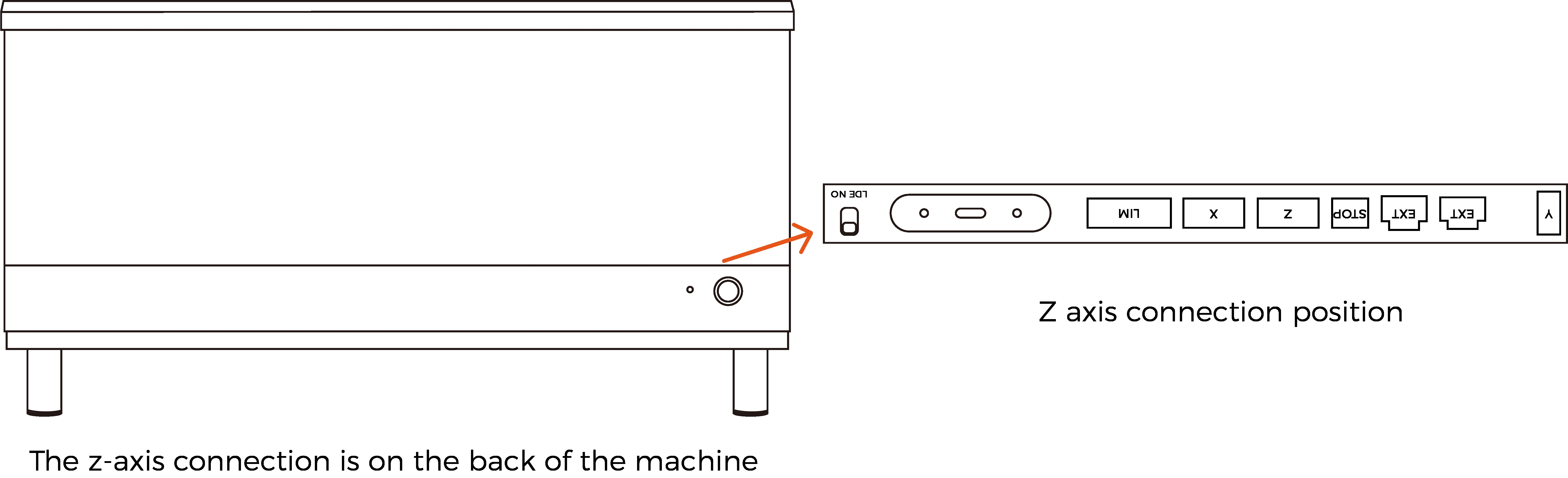
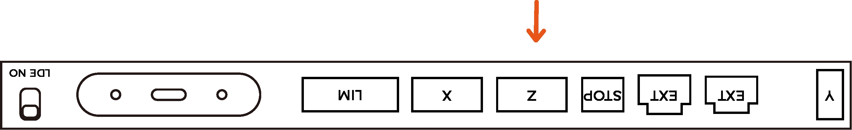
Connect the motor cable plug of TOOCAA 5-in-1 Rotary for L2 to the Z-axis socket of TOOCAA L2.
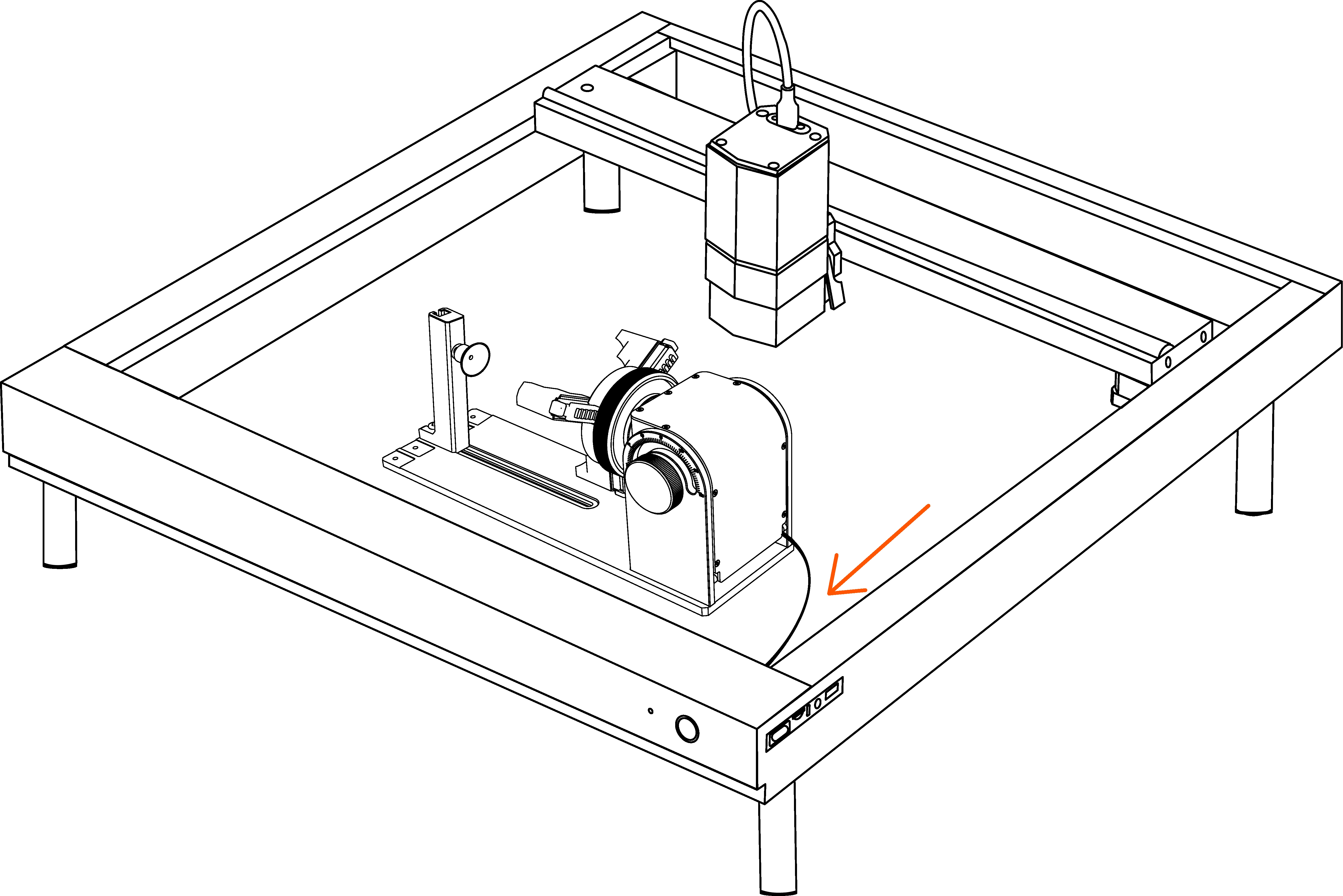
Q&A:__The Z-axis connection of TOOCAA L2 is located on the back of the TOOCAA L2 body.
¶ Focus Operation
Select the appropriate accessories according to the type of cutting/engraving material, and adjust the TOOCAA 5-in-1 Rotary for L2, cutting/engraving material, and TOOCAA L2 machine X-axis to a horizontal and parallel state.
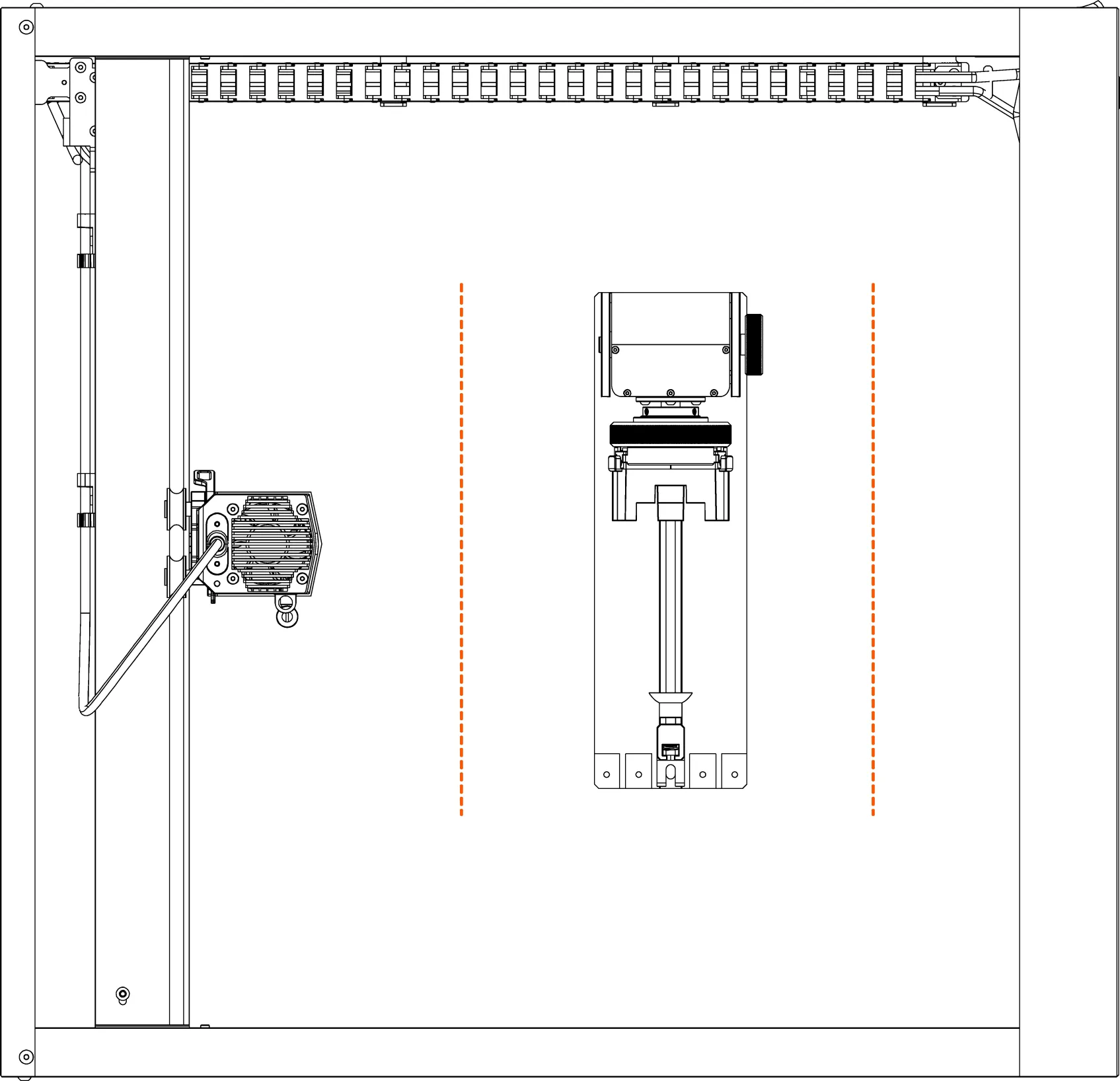
TIPS:You can purchase a level to help confirm whether the cutting/engraving material is in a horizontal state.
Adjust the laser module focus lever so that the tip of the focus lever touches the cutting/engraving material.
¶ Software Operation
¶ Download and verify the configuration file of TOOCAA 5-in-1 Rotary for L2
- Please click the link below to download the configuration file.
Download Link:
https://www.elecfreaks.com/download/toocaa/toocaa5-in-1rotaryforl2configurationfilev1.0.nc
After downloading the configuration file, import it into the TOOCAA L2's built-in SD card, insert the SD card into TOOCAA L2, click the button to return the laser module to its initial position, and then double-click the button to start the machine to complete the configuration file setting.
TIPS:Double-click the button to start the machine and there will be responsive music.
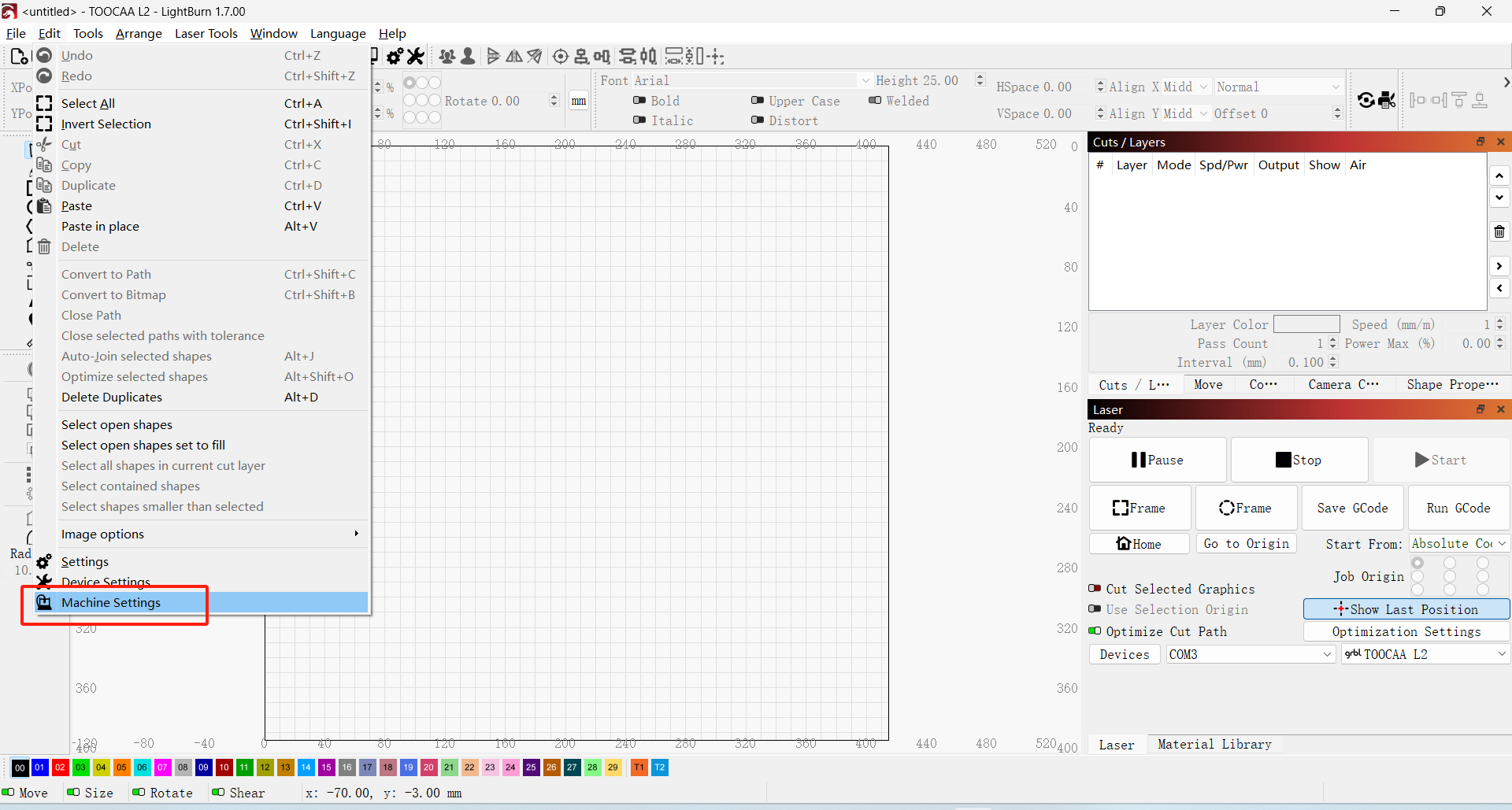
Connect the machine through LightBurn. Click Machine Settings in the Edit window.
Select output settings.
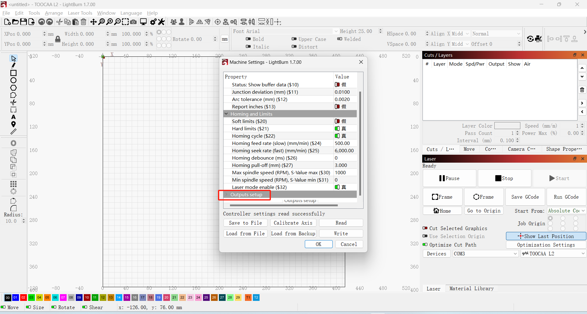
If the suffix of Z Steps per mm ($102) is 100.000, the file configuration is complete and the TOOCAA 5-in-1 Rotary for L2 can start to operate normally.
Note: If the suffix of Steps per mm ($102) is not 100.000, please contact TOOCAA after-sales technicians in time (TOOCAA after-sales technicians contact information:support@toocaa.com). We will solve it for you as soon as possible.
%E5%90%8E%E7%BC%80%E6%98%BE%E7%A4%BA%E4%B8%BA100.000.png)
¶ TOOCAA Studio & TOOCAA 5-in-1 Rotary for L2 Tutorial
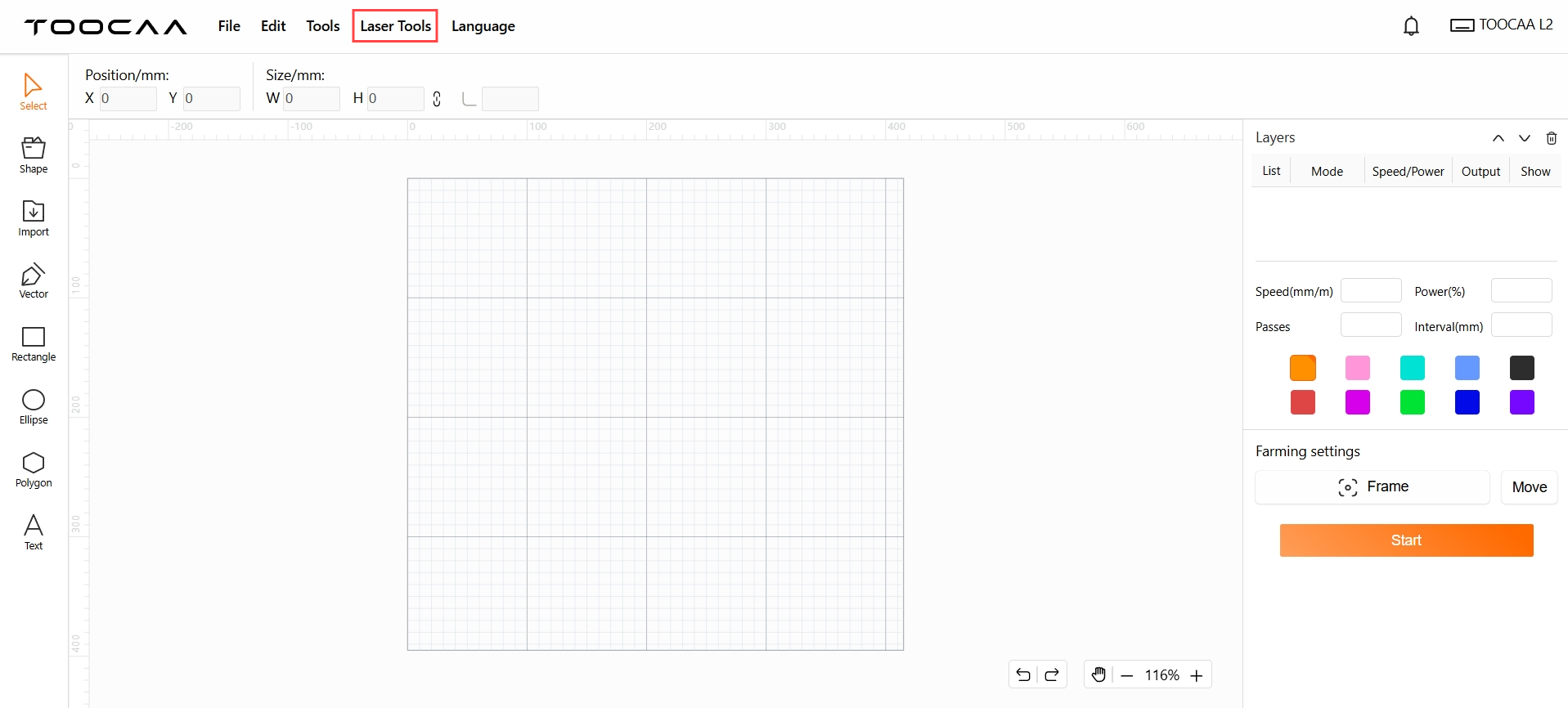
Start TOOCAA Studio.
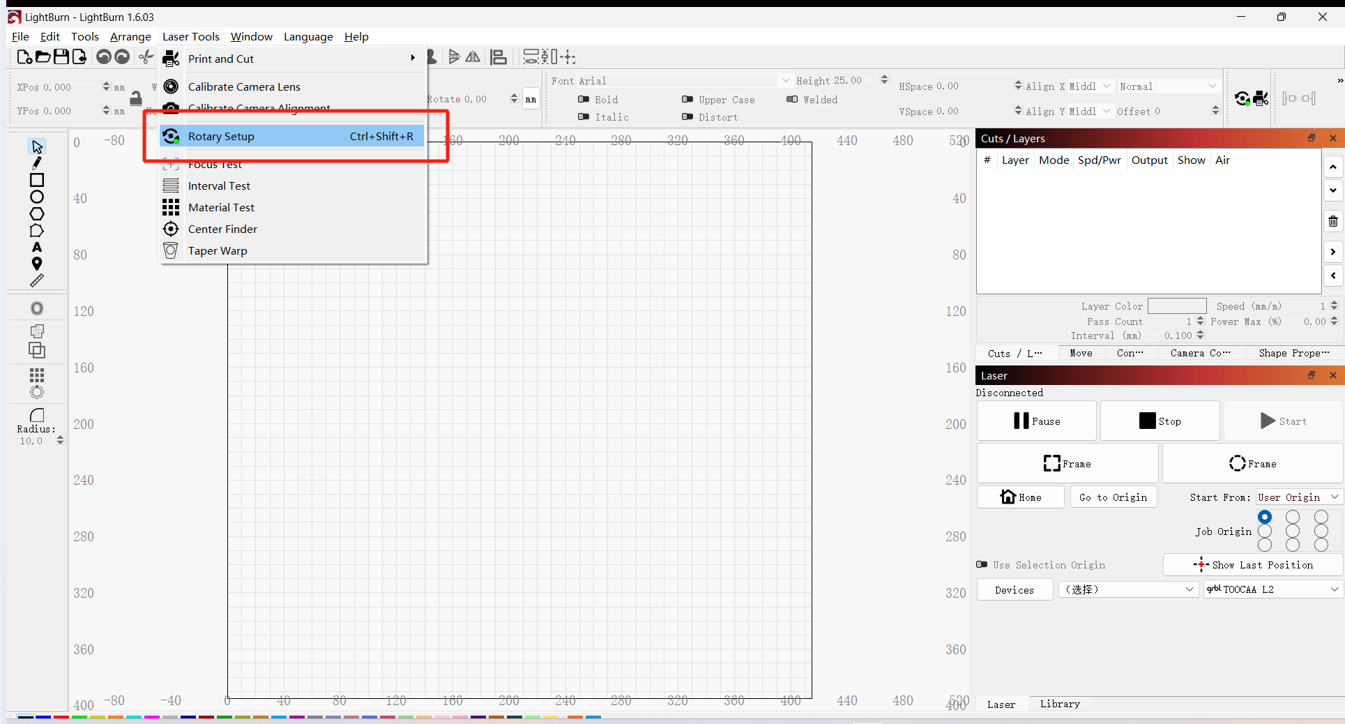
Click Laser Tools in the menu bar.
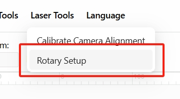
Select the Rotary Setup.
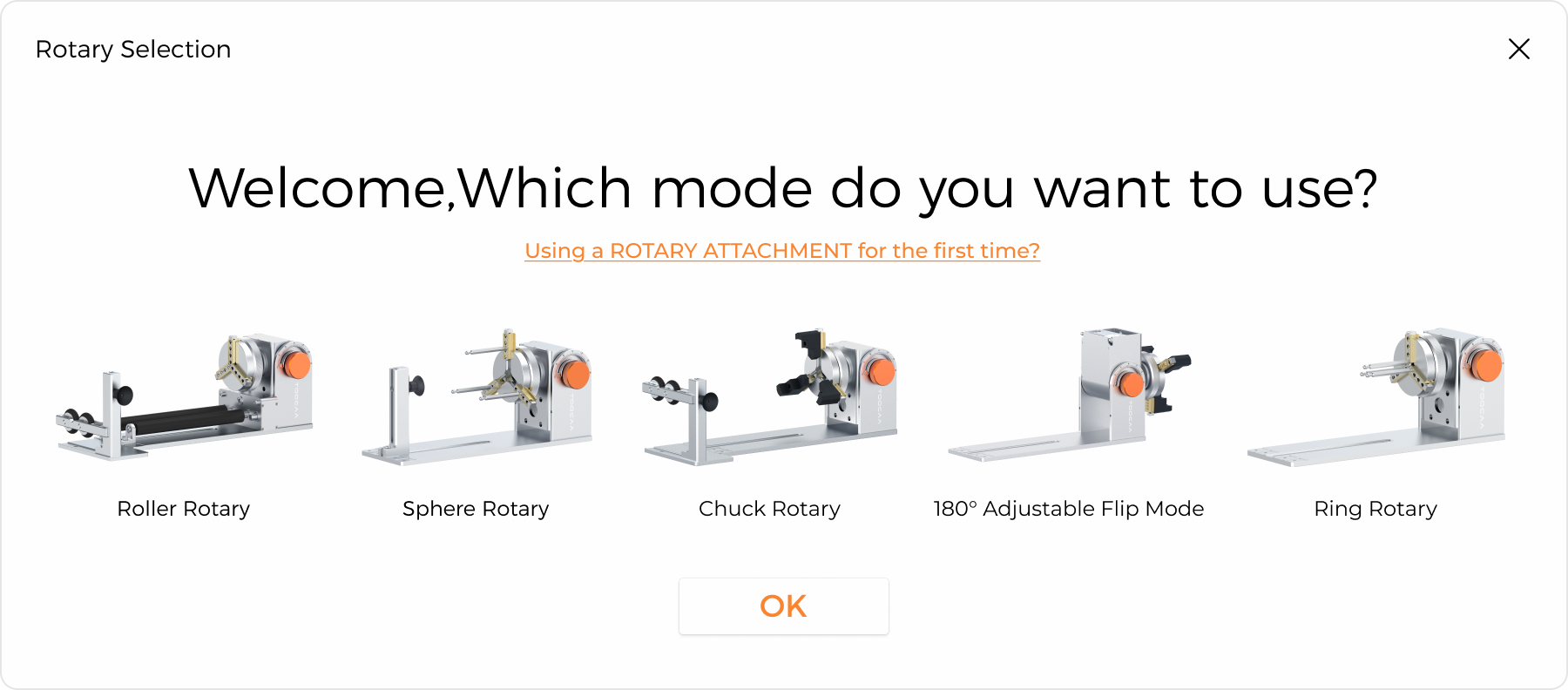
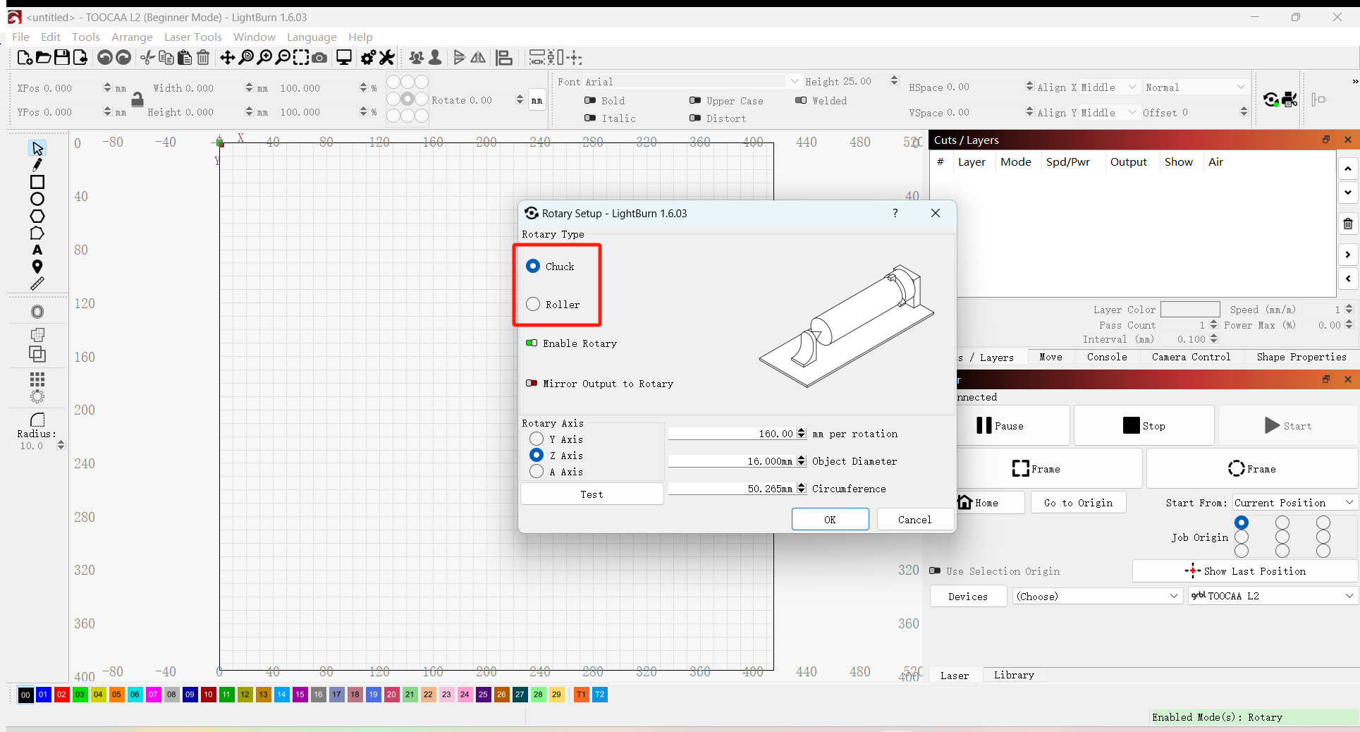
Select the mode you will be using。
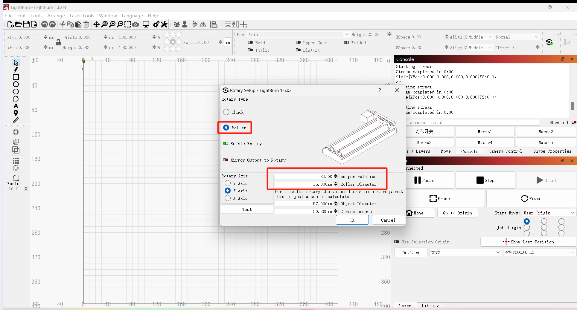
If you select the Roller Rotary mode, just click OK to start using it.
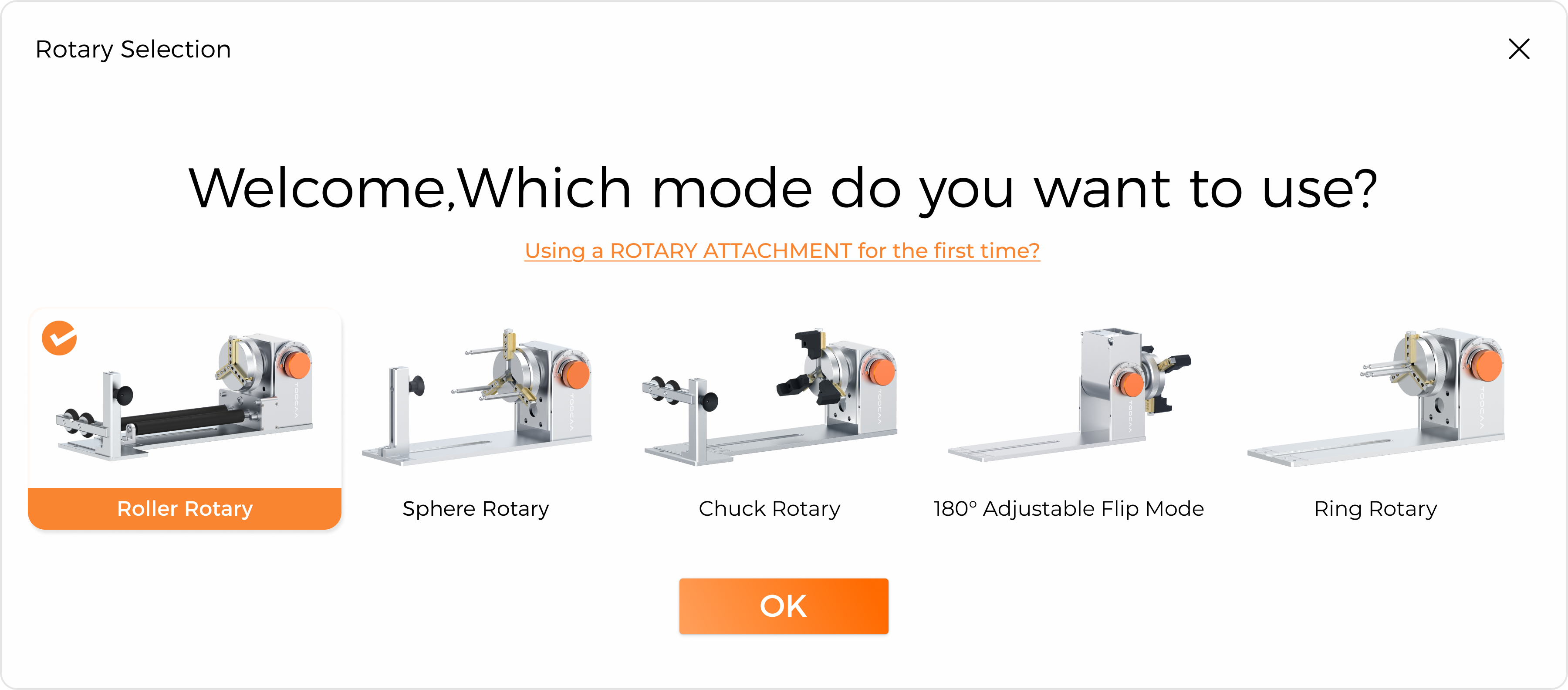
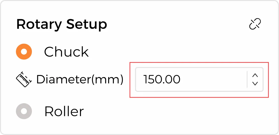
If you select the Chuck Rotary, Sphere Rotary, Ring Rotary, or 180° adjustable flip mode, please enter the object diameter in the rotation accessory toolbar on the right after clicking OK.
Congratulations! You have completed all TOOCAA 5-in-1 Rotary for L2 function settings!
After setting appropriate parameters for the material, perform the Frame operation. If the position meets your requirements, you can click in the lower right corner to start creating.
Notice:
1. After selecting the rotary accessory mode in TOOCAA Studio, the positioning mode automatically switches from absolute coordinates to the current position of the focus lever (relative coordinates). Please pay attention to the position of the object in the canvas to avoid limit errors.
2. In the rotary accessory mode, the laser module's working starting position is the current position of the focus lever (relative coordinate). After using the focus lever to adjust the focal length to the actual filament size, processing can be started directly without the need to move (or return) the laser module a second time.
¶ LightBurn
Notice:
- Make sure you have purchased, downloaded, and installed a genuine copy of LightBurn.
- Before using LightBurn to operate TOOCAA 5-in-1 Rotary for L2, please make sure you have updated the machine firmware through TOOCAA Studio. (To check whether it is the latest firmware, please read this document 《TOOCAA L2 Firmware Version Update Tutorial》
Please click the link below to download the configuration file.
(Configuration file download link:
https://www.elecfreaks.com/download/toocaa/toocaa5-in-1rotaryforl2configurationfilev1.0.nc)
After the configuration file is downloaded, import it into the built-in SD card of TOOCAA L2. Insert the SD card containing the configuration file into TOOCAA L2 and double-click the button to start the machine.
Start LightBurn:
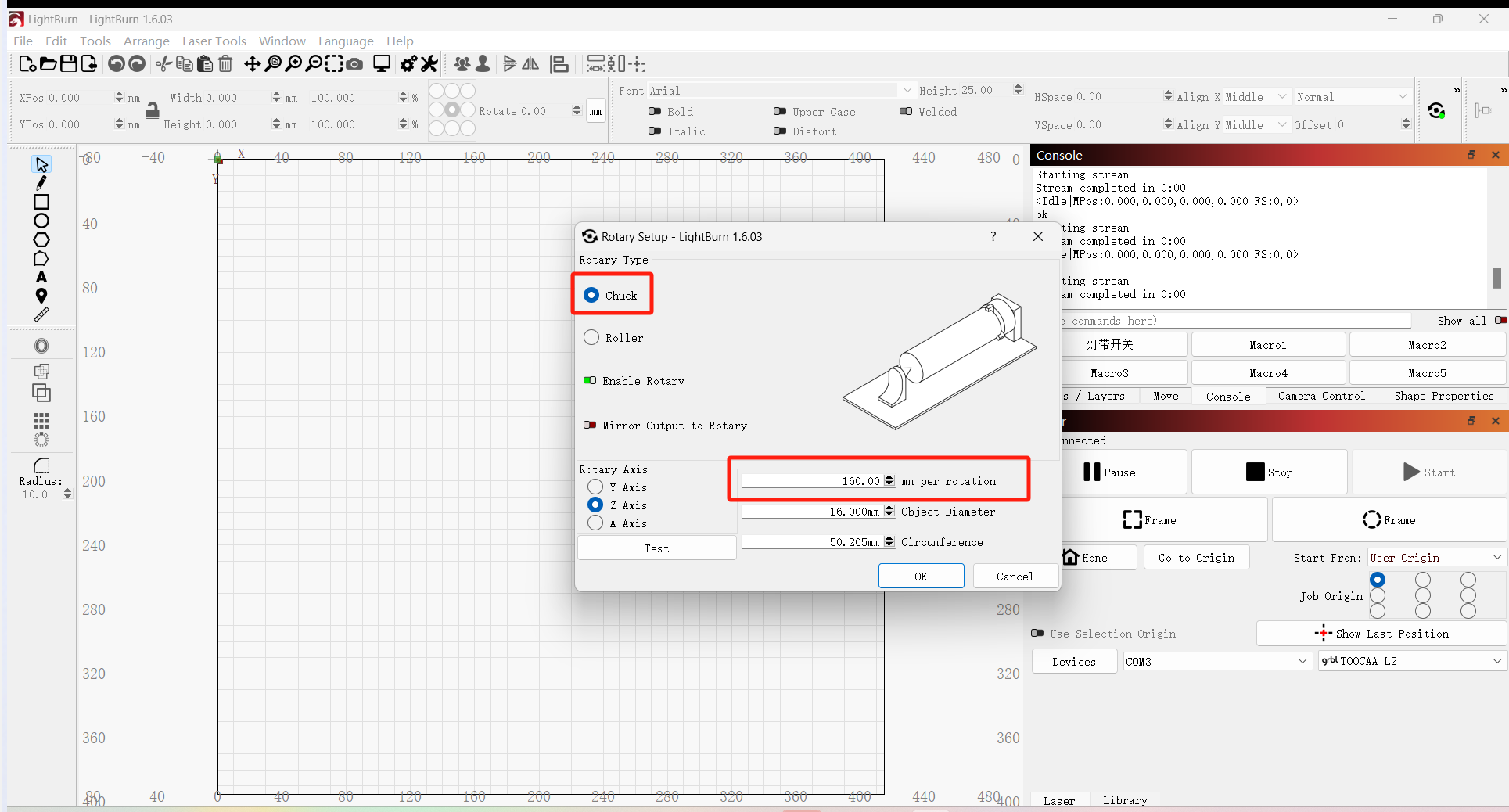
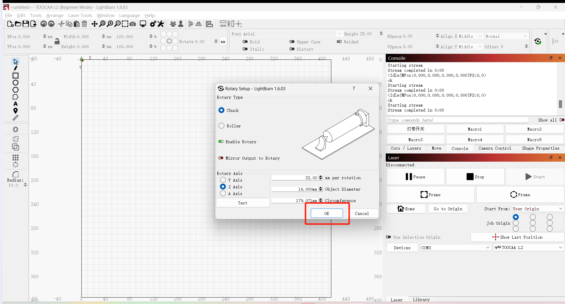
Click Rotary Setup in the Mode toolbar.
Select the type of rotary accessory you want to use (Chuck Rotary or Roller Rotary).
Note:Except for the roller rotary accessories which are of the roller type, the chuck rotary accessories, sphere rotary accessories, ring rotary accessories, and 180° adjustable flip mode accessories are all of the chuck type.
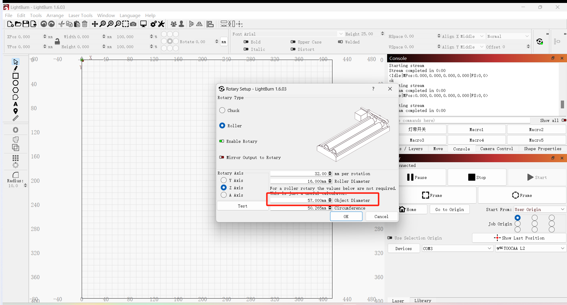
If using a roller rotary accessory mode, please set the Steps per Revolution value to 32.00 mm and the Roller Diameter value to 16.00 mm.
If using a chuck rotary accessory mode, please set the steps per revolution value to 160.00 mm.
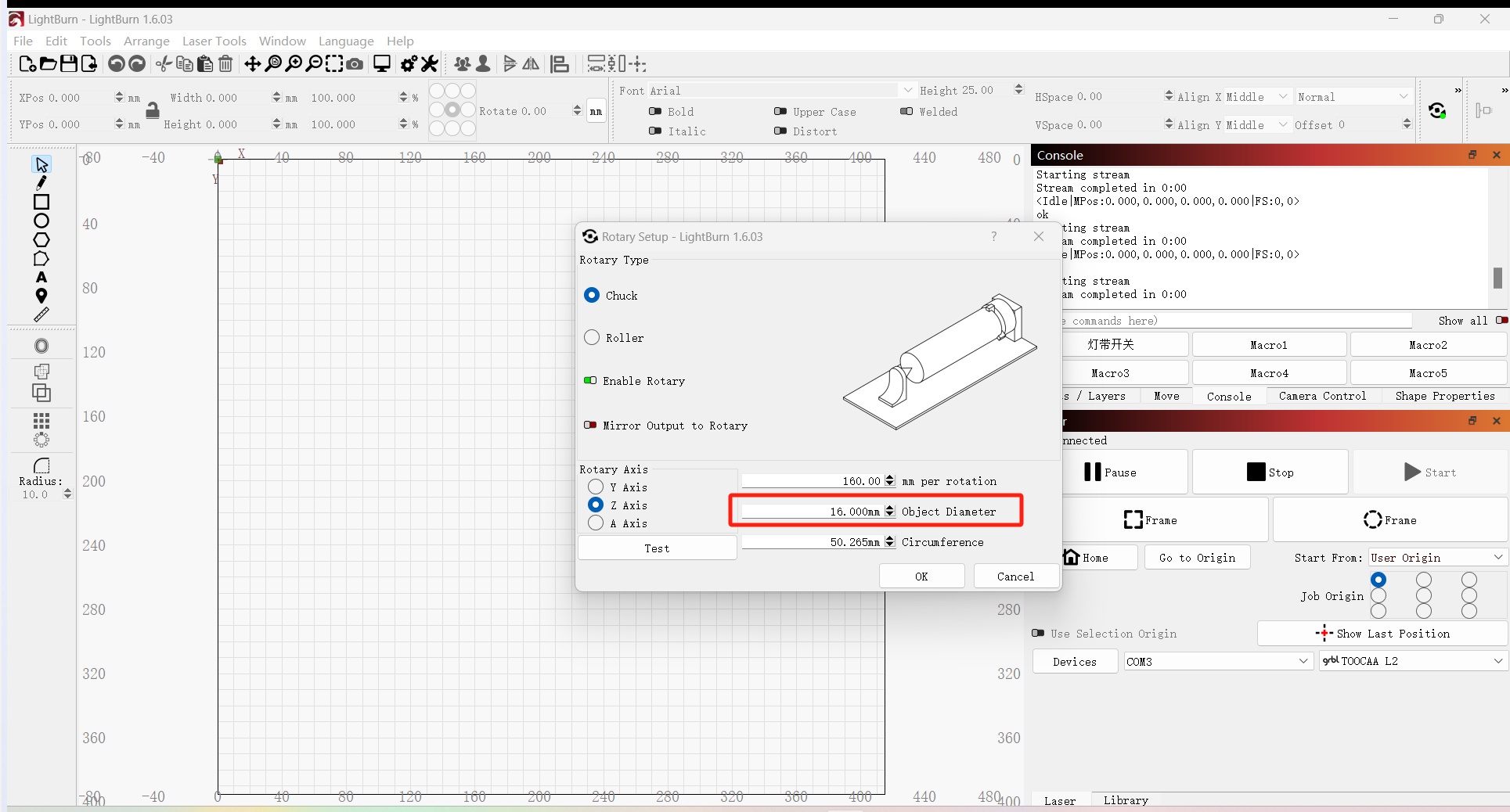
Please carefully measure and enter the object diameter of the item on the rotary accessory. This value must be updated each time you place an object of different diameter on the rotary accessory. If it is not accurate, the engraving result will be distorted or broken.
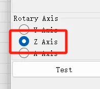
Whether the rotary accessory mode is roller mode or chuck mode, the rotary axis should be the Z axis.
Click the OK button to complete the settings.
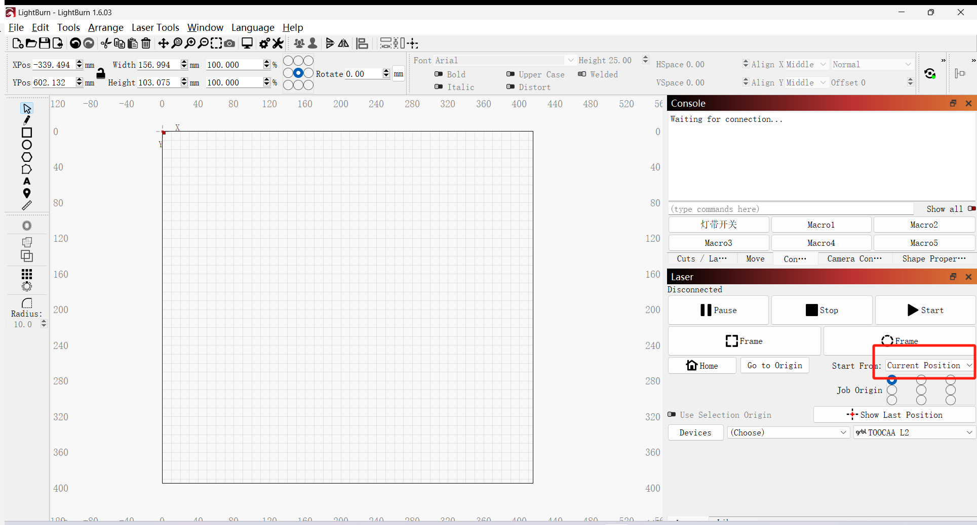
Set the laser module's start position to the current position.
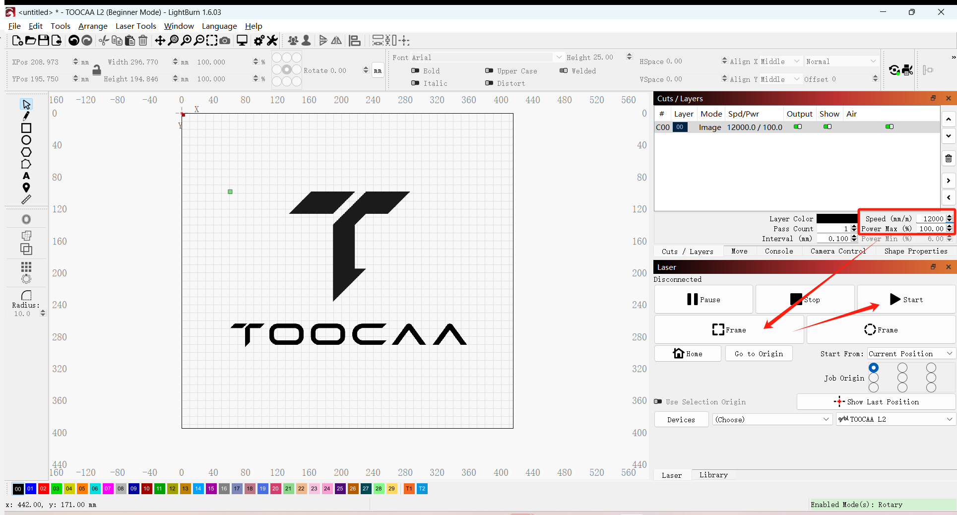
Import the material into LightBurn, set appropriate parameters for the cutting/engraving material, and click Frame test. When the tested position meets the requirements, you can click Start Creation.
Note:In roller rotary accessory mode, the maximum working speed is set to 6000mm/min; in chuck rotary accessory mode, the maximum working speed is set to 12000mm/min. Please reduce the engraving speed according to the material you choose.
¶ FAQ
¶ 1. The rotary accessory does not rotate or rotates irregularly.
- Make sure the machine is connected to the Z axis correctly.
- Check whether the rotary accessory mode on LightBurn and the corresponding parameters of the step value per rotation and the roller diameter value are filled in correctly.
- If you confirm that the machine is connected correctly and the parameters are set correctly, but it still does not rotate or rotates irregularly, please contact TOOCAA after-sales technicians in time (TOOCAA after-sales technicians contact information: zack@toocaa.com), and we will solve it for you as soon as possible.
¶ 2. Why can't the extension double-step jaw components/chuck needle be inserted after pressing the top button of the chuck?
Please adjust the tightness of the chuck knob and then insert the double-step jaw components/chuck needle.
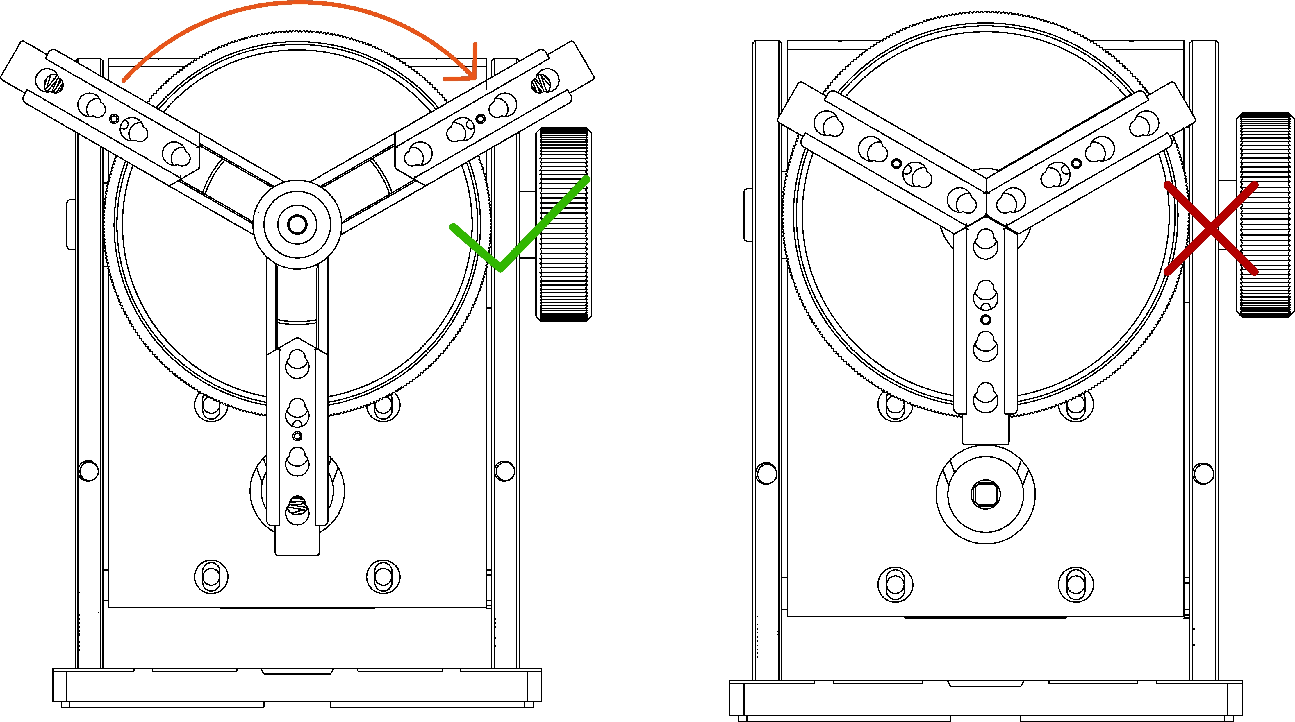
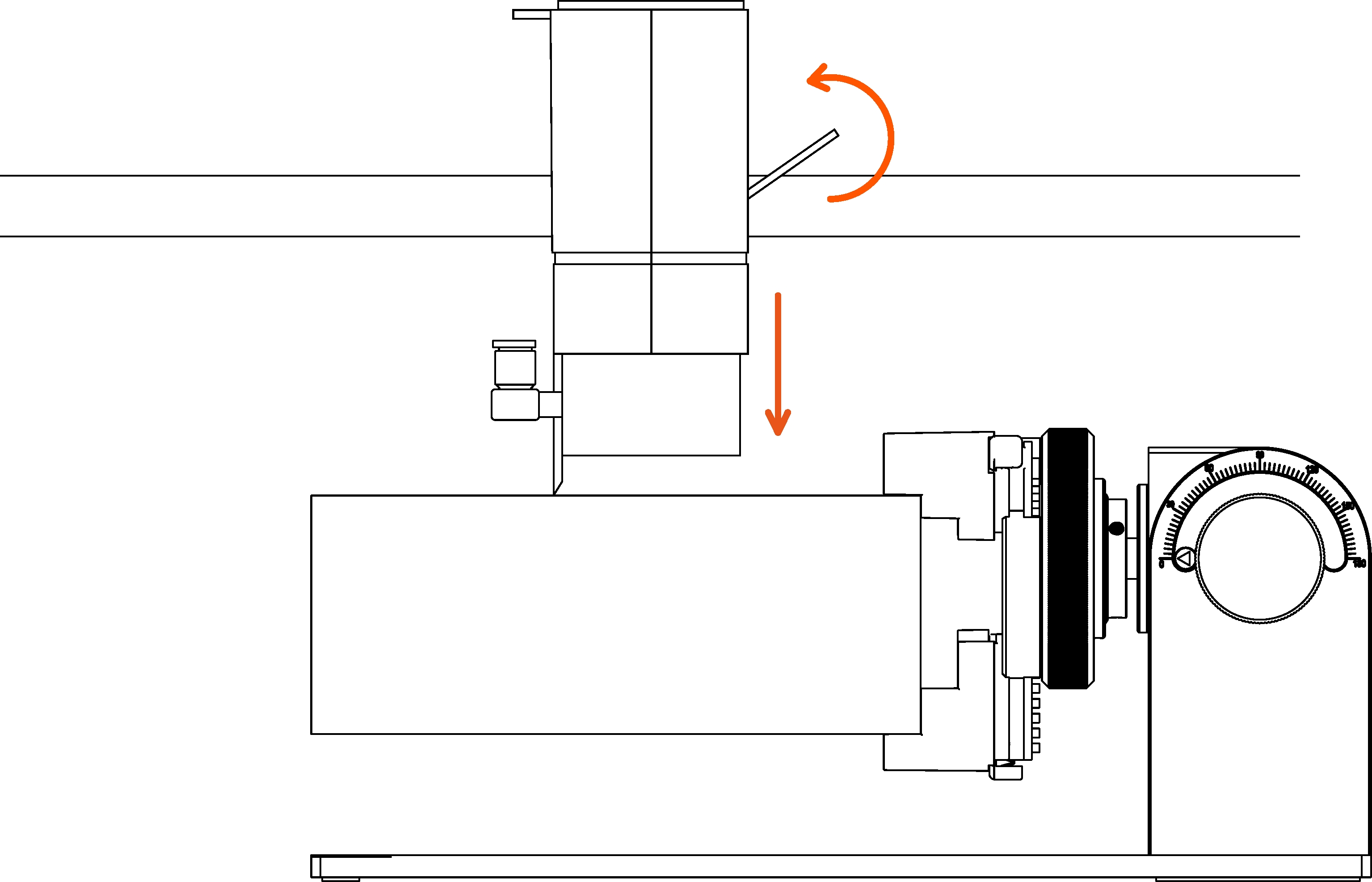
¶ 3. The side knob of the rotary accessory is locked.
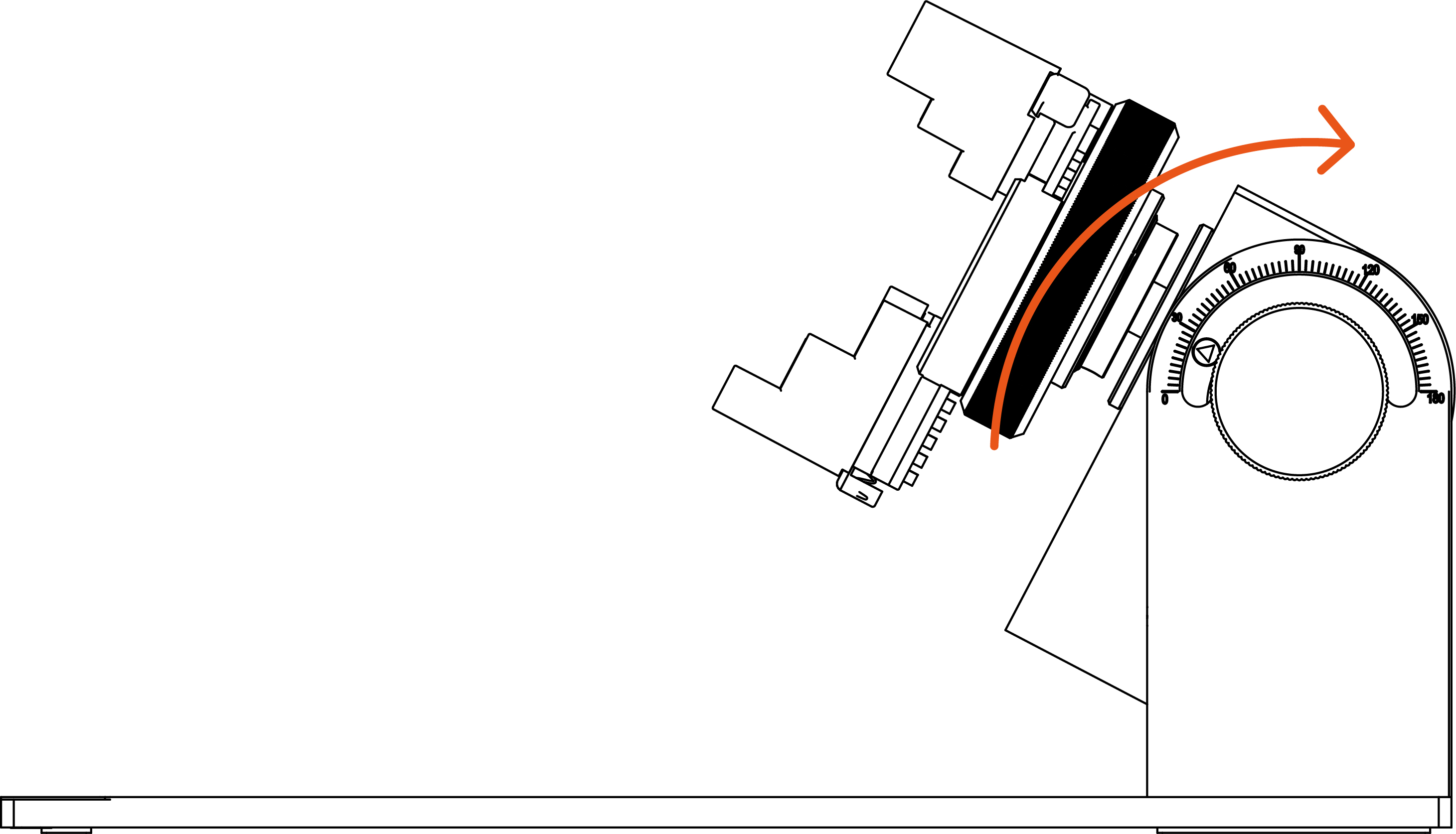
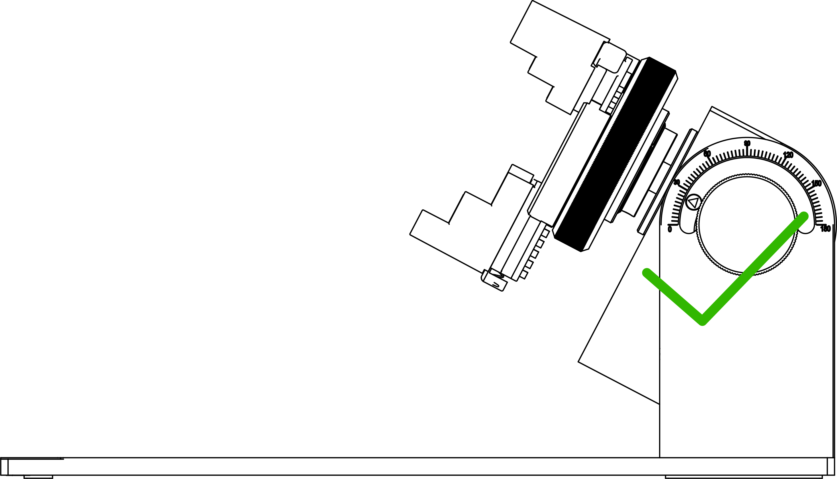
If the side knob is locked and cannot be turned, please turn the rotary accessory body clockwise as shown in the figure below. After adjustment, the side knob can be easily turned.
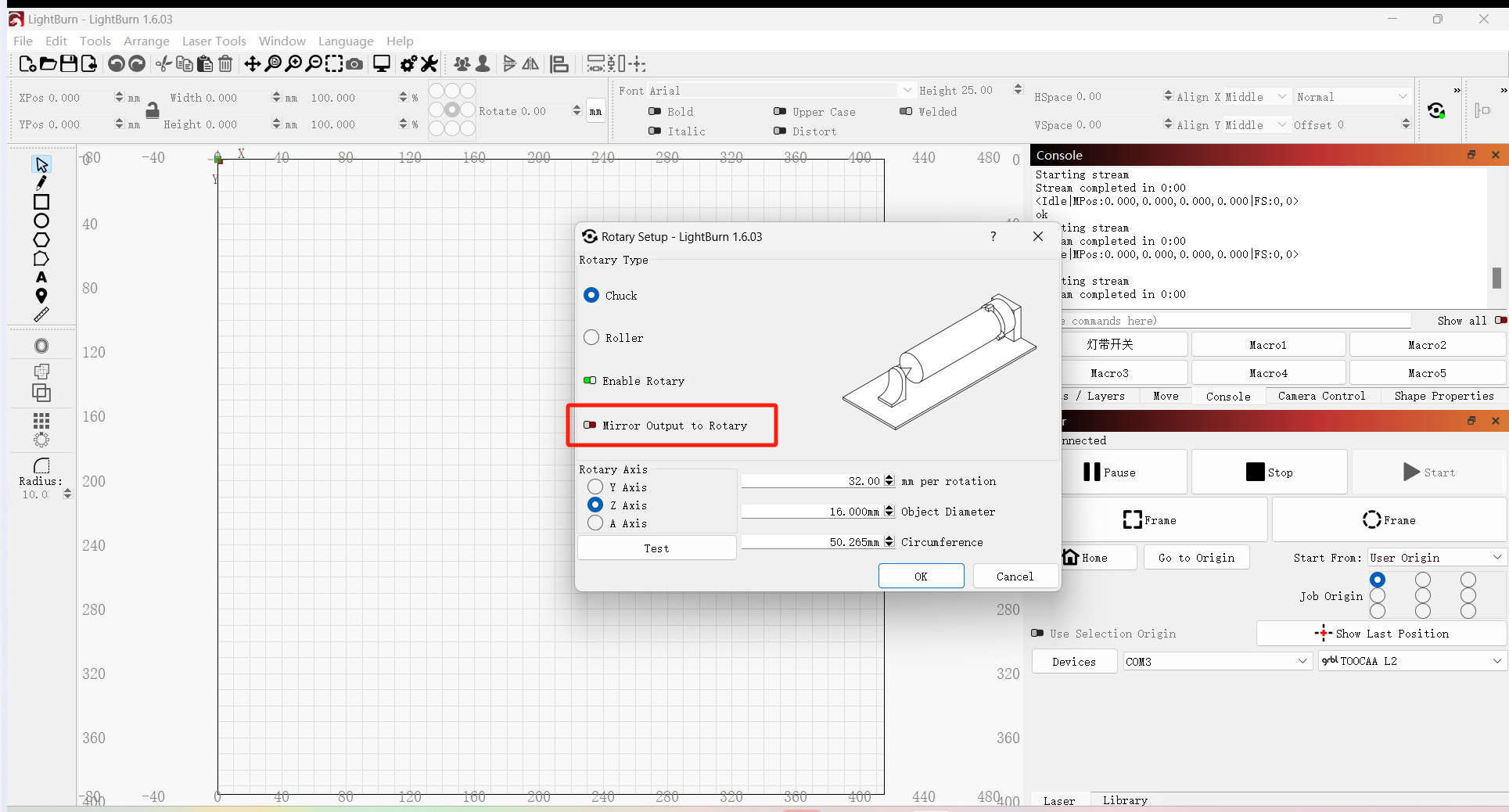
¶ 4. Why does the image appear mirrored after engraving?
Please cancel the 'mirror output to rotary' set when clicking the rotary setup in the mode toolbar to set parameters.
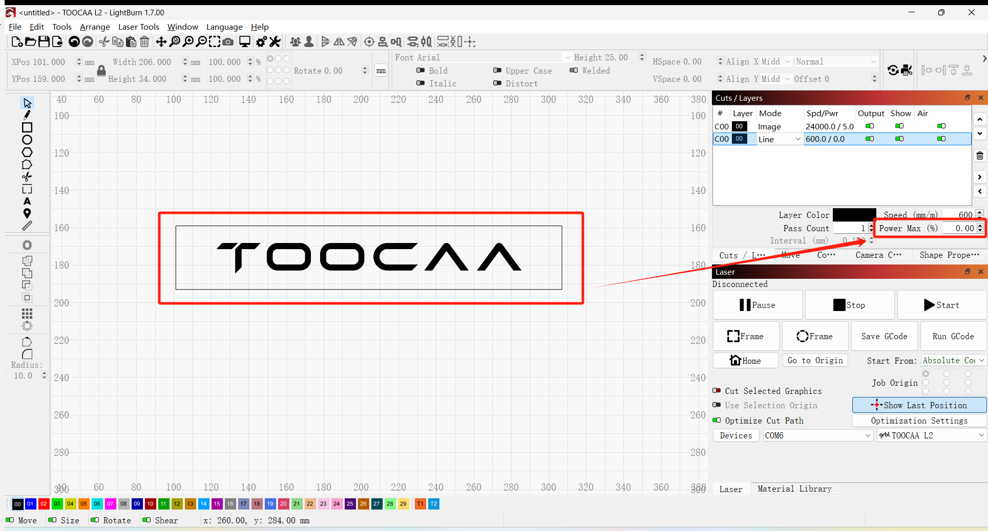
¶ 5. The top or bottom of the engraved image is incomplete.
Please manually set the Z-axis overscan.
How to set: In LightBurn, draw a rectangular frame larger than the engraved image, select Power Max to 0, and then engrave the image.
¶ 6. How to engrave materials with larger diameters (>140mm) using chuck accessories?
If you need to engrave materials with larger diameters (>140mm), it is recommended to use the roller rotary accessory for engraving.
¶ 7. How to use a vernier caliper?
If you have any questions about how to read a vernier caliper, please read the following tutorial document: