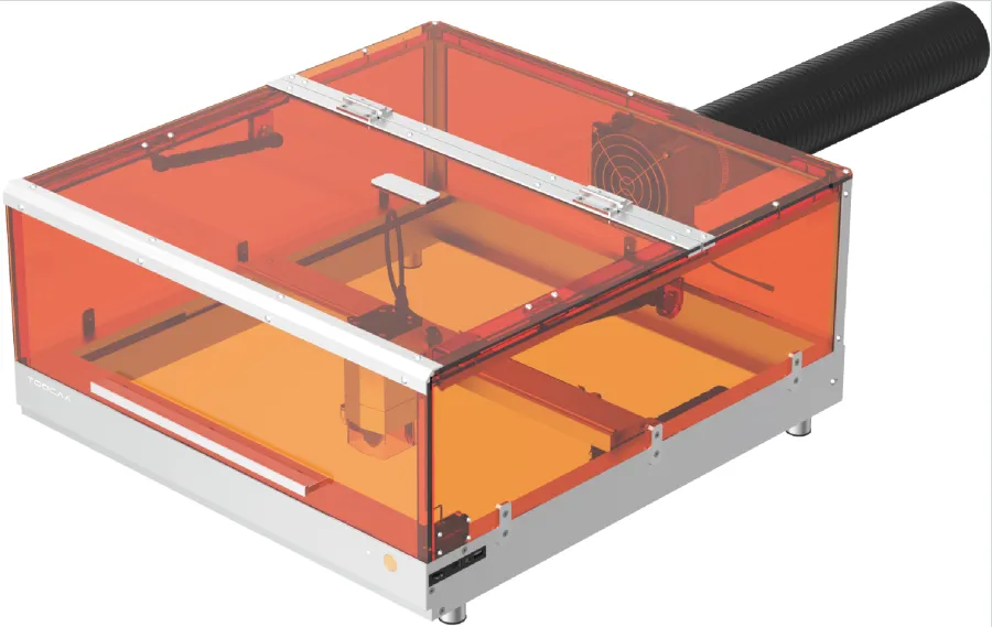
TOOCAA L2 Unpacking Inspection & Assembly
Unpacking Inspection
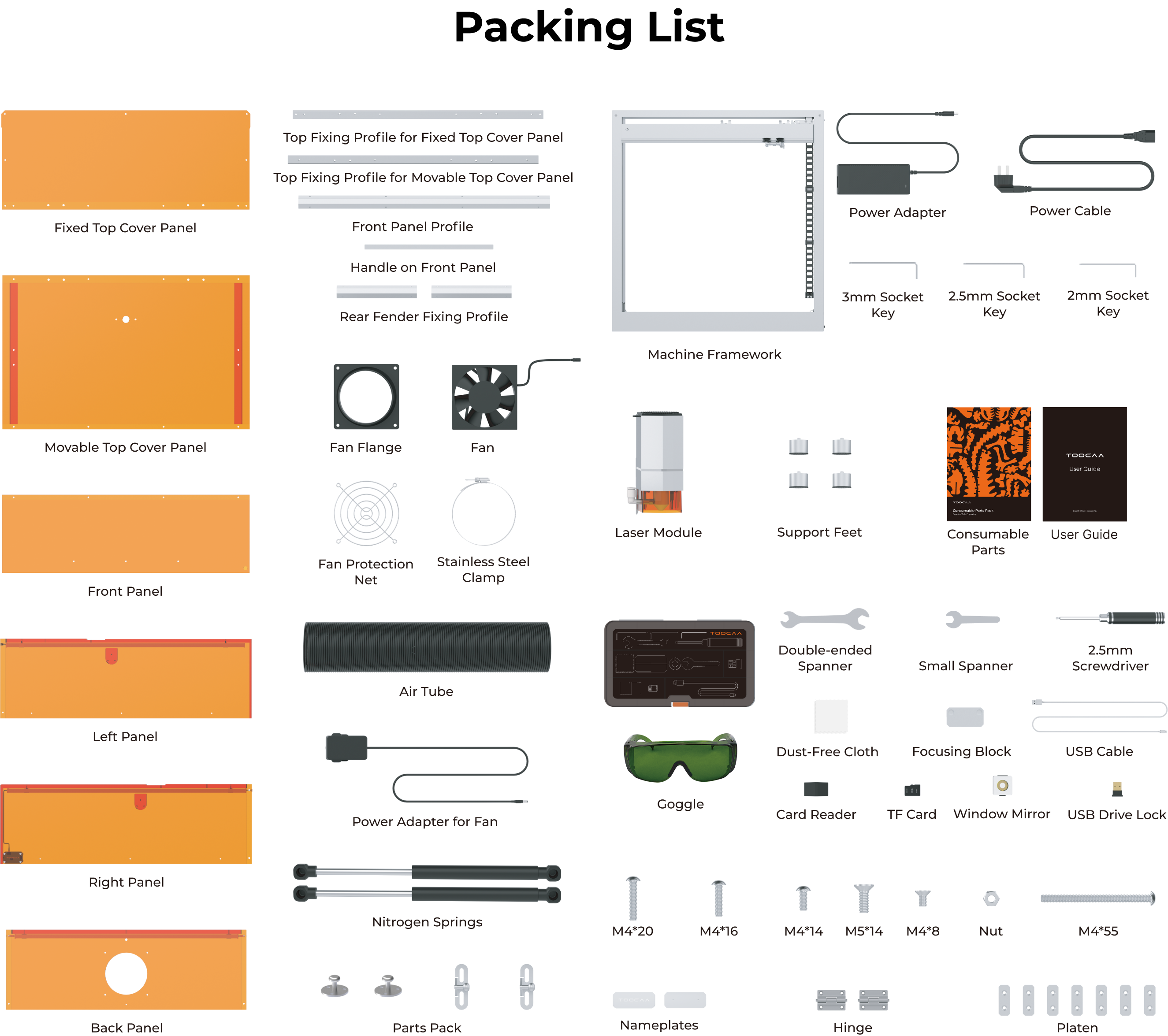
Consumable Parts Pack list
| Type | Size | Quantity |
|---|---|---|
| Linden Wood Board | 210mm × 297mm × 3mm | 1 |
| Gold Aluminum Nameplate | 50mm × 25mm | 1 |
| Sky Blue Aluminum Nameplate | 50mm × 25mm | 1 |
| Stainless Steel Nameplate | 50mm × 25mm | 1 |
| Aluminum Plate | 210mm × 297mm × 0.5mm | 1 |

Assembly and Instruction for Operation
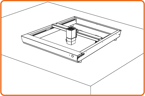 | The laser module will move quickly during operation. It is recommended that the laser cutter be placed on a smooth, wide and tidy table. |
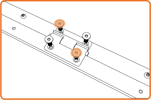 | When installing multiple screws at the same time, it is recommended to pre-lock the screws on the outermost corners first, then pre-lock the remaining screws, and finally lock all the screws in order of pre-locking. |
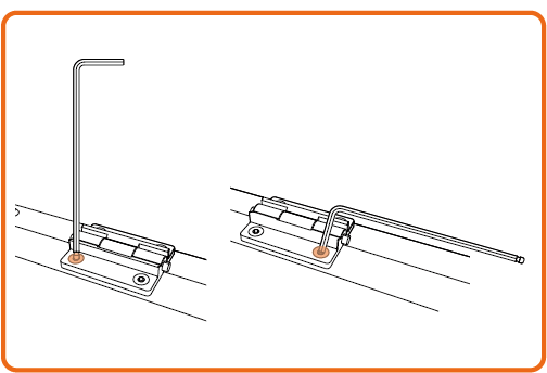 | When installing screws with the socket key, it is recommended that the screws be screwed into the screw holes with the long handle and then locked with the short handle. To remove the screws, just follow the opposite procedure. |
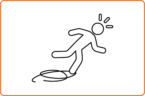 | Please organize and store cables in a timely manner to prevent them from becoming tangled and knotted or tripping people up. |
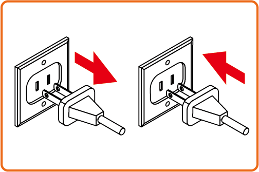 | When the machine is powered on, do not plug or unplug any connecting cables without special instructions. |
Assembly Method
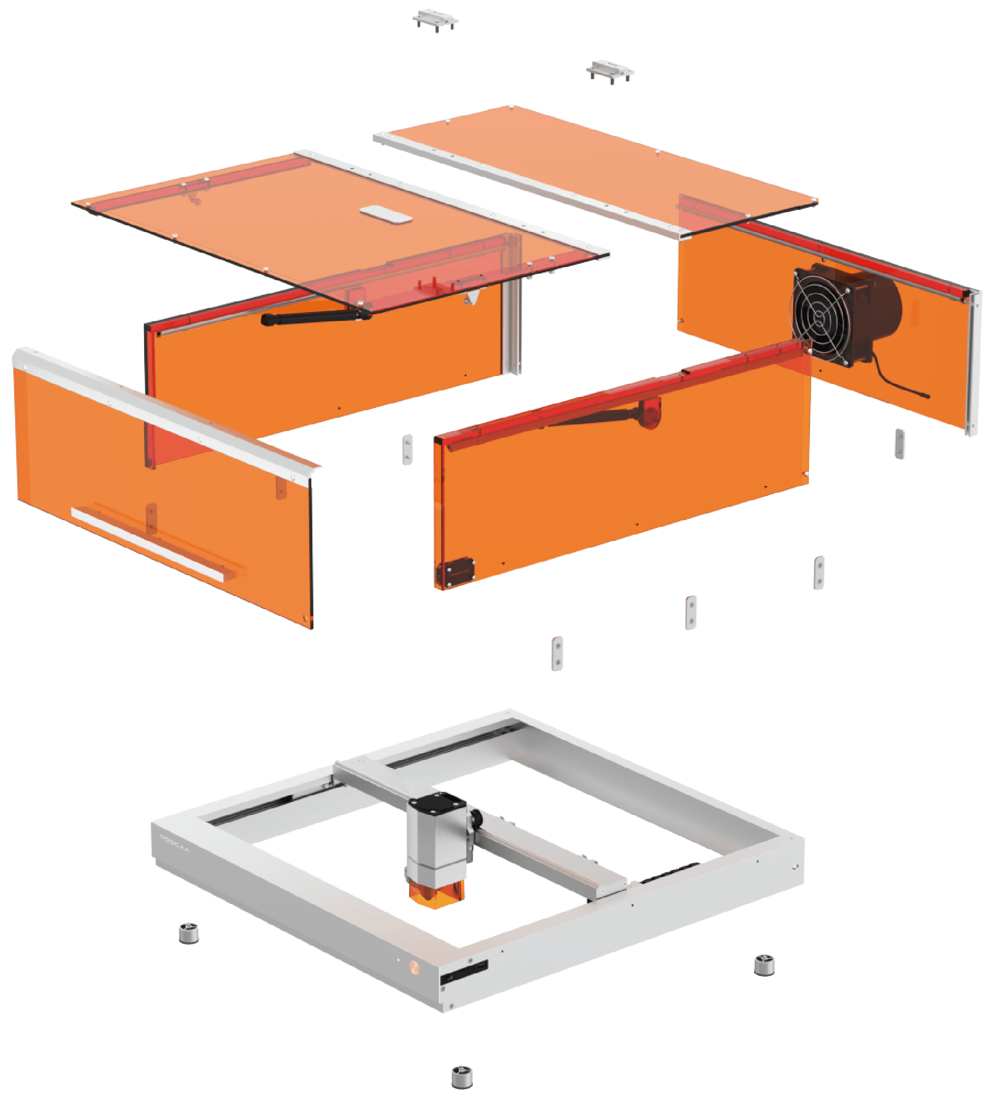
Get and watch the tutorial video by visiting https://www.toocaa.com/blogs/user-guide/basic-user-guide-toocaa-l2-machine-assembly-tutorial or scanning the QR code.

Step 1/32 Lift the machine and install the Support Feet.

Step 2/32 Open the trigger on the X-axis motion assembly.

Step 3/32 Install the laser module.

Step 4/32 Press the trigger to secure the laser module.

Step 5/32 Connect the Type-C cable and lock the screws.

Step 6/32 Use M4*55 screws to assemble the exhaust system on the rear panel.

Step 7/32 Assemble the aluminum profile that connects the back and side panels.

Step 8/32 Use M4*10 screws to lock the back panel and aluminum profile.

Step 9/32 Use M4*10 screws to secure the retaining part of the stop-at-will spring to the left and
right panels.

Step 10/32 Fit both of left and right panels to the aluminum profile on the back panel.

Step 11/32 Use M4*10 screws to secure the left and right panels to the hardware connectors on the back panel.

Step 12/32 Connect the LED strips control cables.

Step 13/32 Mounting and securing profile for the top cover panel.

Step 14/32 Use M4*10 screws to mount profile of fixed top cover panel.

Step 15/32 Install the fixed top cover panel into the groove of the left/right panel against the rear end.

Step 16/32 Use M4*10 screws, mount the fixed top cover panel near the top position of the rear panel.

Step 17/32 Use M4*16 screws, fix the fixed top cover panel profiles to the left and right panels.

Step 18/32 Install the movable top enclosure profile and the nameplates.

Step 19/32 Use M4*10 screws to lock the movable top cover panel and profile.

Step 20/32 Use M4*20 screws, attach the fixed structural parts of the nitrogen spring to the movable upper cover panel.

Step 21/32 Place the movable top cover panel onto the left and right panels.

Step 22/32 Place the movable top cover panel onto the left and right panels.

Step 23/32 Use M4*10 screws to assembly the front panel profile to the front panel.

Step 24/32 Use M4*10 screws to attach the handle to the front panel.

Step 25/32 Assemble the front panel profile to the movable top cover panel and lock it with M4*10
screws.

Step 26/32 Install the nitrogen springs to the left and right panels.

Step 27/32 Install the nitrogen spring onto the movable top cover panel.

Step 28/32 Place the smart enclosure on the machine.

Step 29/32 Use M4*8 screws to attach the platen kit to fix the machine and smart enclosure.

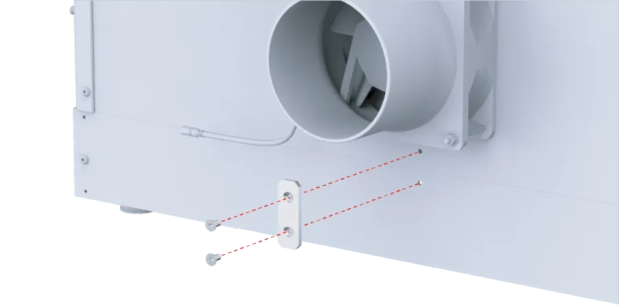
Step 30/32 Connect the control wires of the LED strips.

Step 31/32 Use stainless steel clamps, mount the duct to the fan flange.

Step 32/32 Tighten the stainless-steel clamps.

